Frequency Track
Frequency Track Description
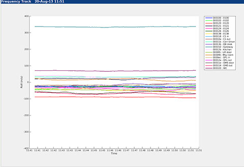
This technical chart is used to display the frequency tracker performance. The frequency tracker is part of the Timing Model that makes up part of the Omnisense Joint Timing and Location Engine that is used to solve for position given a number of observed time-of-arrival measurements.
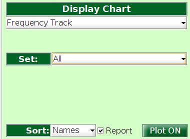
Each device in the selected Set under options is drawn as a line trace with colour as shown in the legend to the right of the chart.
The Y axis is the frequency offset expressed as an apparent velocity in metres per second. Without correction this phantom observed velocity would cause very large positioning errors.
The frequency offsets that are plotted are all relative to the network as a whole - there is no single reference, and no one device is used as the baseline frequency; therefore the timing model has no single point of failure which means that adding or removing any device from the network does not impact the overall performance of the other device or the network as a whole.
This chart is intended as a diagnostic tool for use by expert users when configuring and testing the system, or when trying to diagnose system errors.
Frequency in ToF Systems
In Time-of-Flight systems, such as Nanotron swarm bee, the frequency track chart has no meaning because with ToF it is not necessary to solve for the clock offsets between devices. The process of making a Time-of-Flight measurement eliminates the effects of clock offsets between devices - but at the expense of a longer measurement cycle that may seriously limits the ability to scale to large networks in comparison with ToA (Time-of-Arrival) systems.


knowhere anywhere
3rd Floor, St Andrew's House, 59 St Andrew's Street, Cambridge, CB2 3BZ, UK
tel: +44 1223 651390, email: info@omnisense.co.uk
Copyright © 2016, Omnisense Ltd