Orientation for multiple nodes
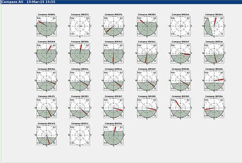
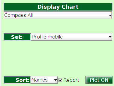
This chart displays a set of charts, one for each device on the selected list as an array of miniature charts.
Each chart has the same format and interpretation as Orientation chart on the Node Sensor plot. It consists of a direction indicator and and artificial horizon showing pitch and roll of the node.
This chart is useful to compare the orientations of multiple devices in real-time and also for calibration of the internal compass.
Compass All
Calibrating the compass : S500
The device compass may be manually calibrated using the following procedure:
- With the device away from any sources of strong magnetic fields such as power leads, metal objects, computer screens etc., and on a working network.
- Hold it upright.
- After each set of LED blinks rotate if clockwise ninety degrees.
- When a full 360 degree rotation has been completed the red LED will be flashing very fast (it looks as though it is vibrating).
- Tumble the device smoothly through all possible orientations in a 3D figure 8 pattern.
- When the LED stops flashing the compass is calibrated.
If rotating the device fails to put it into calibration mode try rotating it the other way, or try rotating it more slowly, waiting two LED pattern blinks between each rotation.


knowhere anywhere
3rd Floor, St Andrew's House, 59 St Andrew's Street, Cambridge, CB2 3BZ, UK
tel: +44 1223 651390, email: info@omnisense.co.uk
Copyright © 2016, Omnisense Ltd